
RW Railway Technology
Railway protection.With insight and control.
Protect.High‑performance voltage limiting devices.
Measure.Real operating data from your railway infrastructure.
Control.Forced VLD switch‑off with RWVLM FT.
More capability for your railway application.
The new HP models advance the market-leading 25 kA platform to 34 kA at 50 ms.
The world's highest recoverable short-time current in VLD Class 2.
DC traction · Class 2.1
RWVL2.1HP
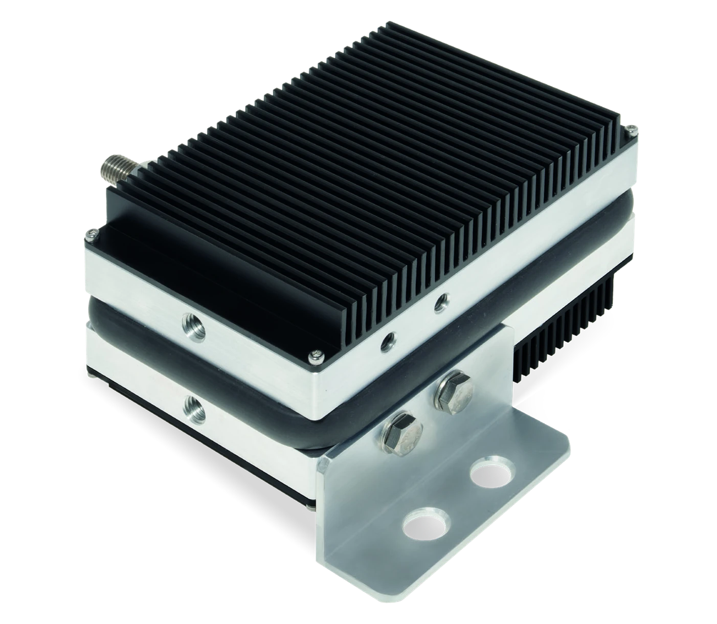
Recoverable short‑time current
One primary switching polarity for DC traction.
Explore RWVL2.1HPDC and AC traction · Class 2.2
RWVL2.2HP
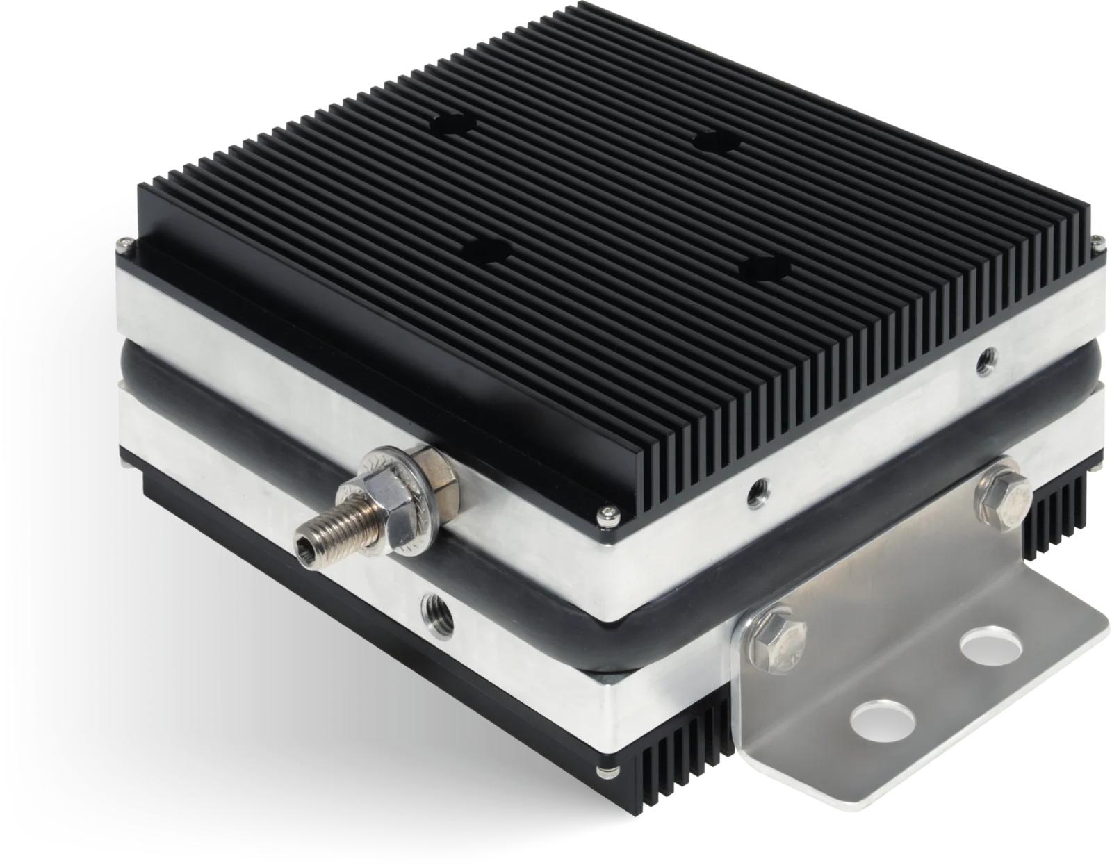
Recoverable short‑time current
Bipolar operation for both voltage polarities.
Explore RWVL2.2HPMeasurement and control
RWVLM
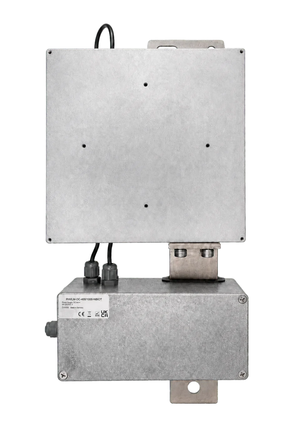
Online Measurement and Monitoring
Rail‑to‑earth voltage, VLD current and fault alerts. FT adds a built‑in forced switch‑off mechanism.
Explore RWVLMExplore the technology
Protection. Measurement. Control.
Select a function to see how the equipment works.
Protection when voltage conditions demand it.
A VLD establishes a conductive connection when its triggering conditions are reached, limiting the voltage difference between the railway return circuit and protected structures.
- Class 2.1: one primary switching polarity for DC traction
- Class 2.2: bipolar operation for DC and AC traction
- New HP models: recoverable current of 34 kA at 50 ms
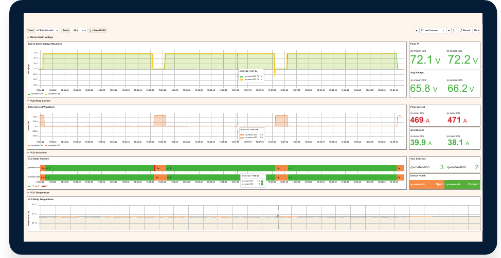
Understand what happens on the railway.
Read rail‑to‑earth voltage and VLD current together to understand activation events and operating behaviour.
- DC measurement ranges: ±400 V and ±1000 A
- 1‑second sampling interval
- Email, SMS and system alerts when a fault is registered
Monitoring that can also force VLD switch‑off.
RWVLM FT contains its own switch‑off mechanism. It can force the connected VLD to switch off, including VLDs from other manufacturers, without a dedicated control function in the VLD itself.
- Forced switch‑off hardware integrated in the FT version
- Specified switch‑off current range: 20–80 A
- Measurement, monitoring and VLD control
From technical questions to practical solutions.
Technical knowledge
VLD principles, current ratings, monitoring and stray‑current corrosion.
Read the technical guideNews and events
Product developments, industry events and updates from RW.
See the latest updatesProject cooperation
Application review, product selection and integration with your railway infrastructure.
Discuss your projectTell us about the traction system, expected current profile and monitoring requirements. We will help you select the appropriate equipment and configuration.
Contact technical sales