(Where you may / may not use the class 1 VLD)
The main purpose of the VLD class 1 is the protection of passengers and infrastructure against excessive touch voltage and overvoltage caused by fatal failure (therefore VLD-F) of traction power supply infrastructure.
New innovative construction
Based on many years of experience of our R&D with VLD applications and the requirements of most customers, the RW company has developed a new, modern Voltage Limiting Device (VLD) class 1, with the possibility of remote indication of the VLD status. The current practice of DC and AC systems uses VLD-F designed on the basis of a gas discharge tube connected to an automatic short-circuiting device, which in the event of a fatal traction fault always operates in a non-repeatable mode, i.e. it goes into a permanently conductive state. This complies with the requirements of EN 50526-2 and other standards. However, if such an event occurs, a permanent short-circuit opens up between the isolated rail and the ground, through which stray currents escape permanently. This permanent current leakage has a very adverse effect on the service life of the metal infrastructure (poles, bridges, waiting shelters, cables, reinforced concrete structures, etc.) alongside the railway track due to electrochemical corrosion caused by the current flow.
Current solutions offer only one way to minimize this damage, consisting in frequent physical inspection of the installed VLD-Fs, which is a challenging task because a reliable verification of the function necessitates to disconnect the VLD from the rail, perform impedance measurements with a sufficiently powerful current source, followed with reconnection of the VLD-F to the rail. This takes quite a lot of time (min. 10 minutes for approx. 3 workers) and costs considerable operating money (OPEX), so that the intervals between checks are often extended and the risk of damage to the infrastructure increases disproportionately. The new, patented VLD-F solution means revolutionary changes in the use of VLD-F and elimination of the complications associated with it.
The short-circuiting device inside the new RWVL1 family is of special design that reacts very quickly to the current flowing through the discharge tube and, at the moment of its overload or destruction threat, shunts it out and ensures a permanent shortcircuit with minimal energy loss so that there is no physical damage to the product housing that could be dangerous to the environment. This short-circuiting device is wirelessly connected to detection electronics that registers such a change and is capable of permanently indicating it. The electronics consists of a patented overload sensor and wireless transmitter.
Status change of sensor is regularly transmitted through long range wireless access network to an evaluation server which provides the operator with information about the status of VLDs across the entire railway network. This information allows the operator to react immediately (replace the VLD) and minimize leakage, corrosive currents through the activated VLDs.
Another significant advantage of this solution is the significantly simpler and more transparent logistics, because in addition to the indication of immediate necessity to replace the VLD-F, other identification parameters of the VLD to be inspected (e.g. serial number, installation coordinates, etc.) are stored in the server memory, which can then be used as a basis for operational statistics, analyses, etc.
The use of this modern VLD-F therefore results in a significant reduction of operating costs for the management of the railway protective bonding system, a minimization of stray currents and thus an increase in the lifetime of railway, which applies also to thirdparty infrastructure last but not least the possibility of advanced analyses entering predictive maintenance systems for the purpose of inspection optimization and further reduction of operating costs. The integrated
protection against lightning and industrial short-term pulses is of course integrated into the product.
Where I can and cannot apply the VLD-F?
For many years it has been common practice to install VLD-F anywhere alongside DC and AC powered railway lines. This installation has often not been associated with infrastructure corrosion problems. With increasing traffic on the lines, changing power supply infrastructure and train propulsion systems, there appear more and more frequently infrastructure
failures and damages that can be clearly attributed to improperly installed VLD-Fs designed on the basis of gas discharge tubes (GDT). The crux of the problem lies in the combination of the behavior of GDT at different voltage levels. The following figure shows a typical limiting characteristic of a GDT:
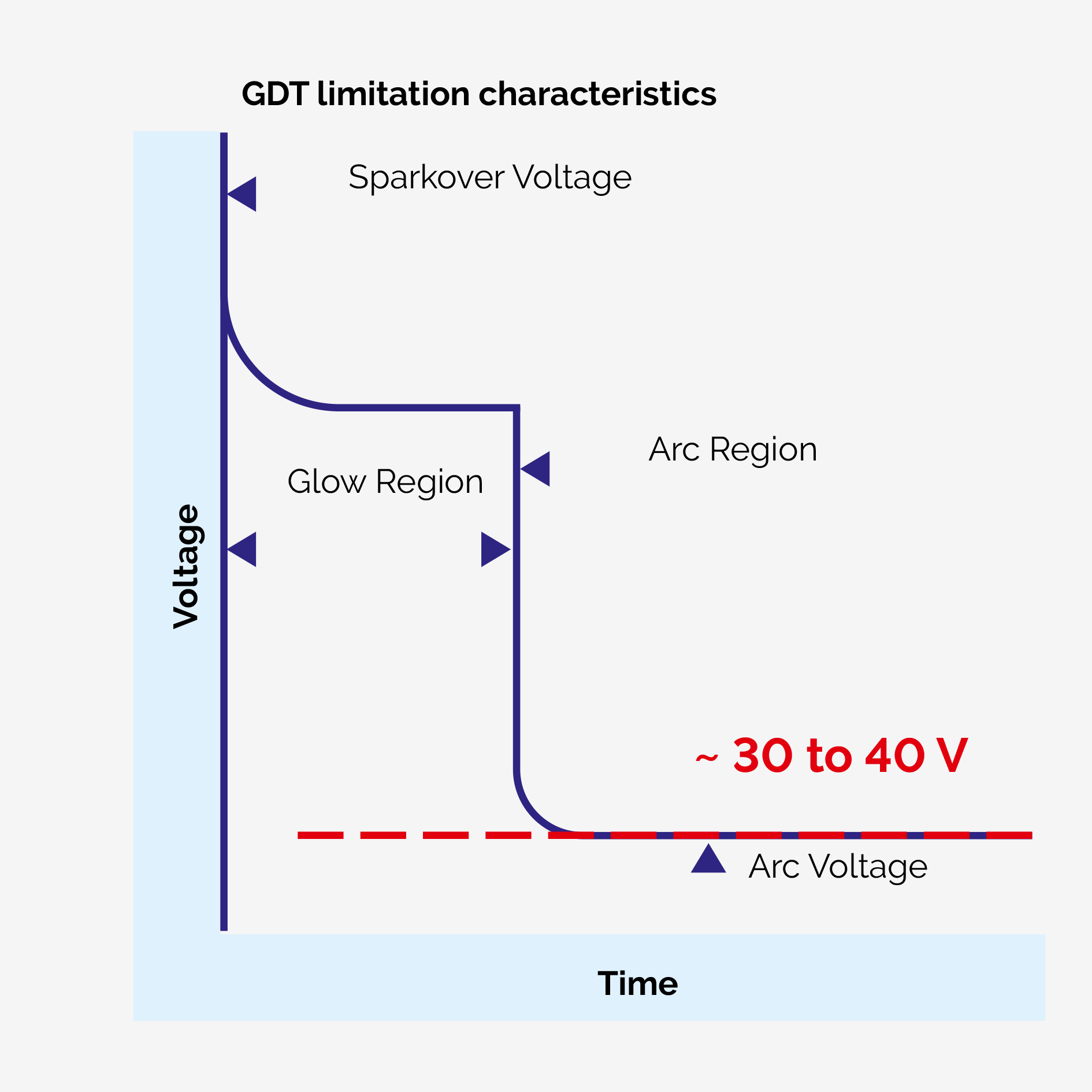
After the arrival of a triggering pulse, the internal space of the GDT passes into the burning arc phase (after a short period of glow-discharge). This arc features specific voltage parameters – depending on the type of lightning arrester, the arc burning process stabilizes the voltage between the GDT terminals (and thus the terminals of the whole product) at a level of around 30V (depending on the arc length). This is the basic principle of GDT voltage limitation, of course, but also the basis of the problem in some applications, specifically there where, for whatever reason, the voltage potential of the track (rail) exceeds the 30V level. The causes of such a condition are varied and often difficult to identify, but result in fatal destruction of the VLD.
At the moment when the trigger pulse activating the opening of the VLD disappears (it can be a very short pulse of higher voltage, since GDT react within nanoseconds), but simultaneously a potential higher than the voltage of the burning arc (30 – 40V) is present on the track, then usually the “hard” source of this potential takes over the role of energy supply of the already burning arc and it burns often for tens or hundreds of seconds. At these voltage and current levels, usually in the order of tens to hundreds of amperes, inevitably results in thermal overload of the GDT, its electrical and mechanical destruction and often (but not always!) physical destruction or damage to the entire VLD. This often causes the VLD to „secretly“ become permanently conductive and the problem is only discovered by the next physical inspection and measurement, which often is too late from a corrosion perspective. This undesirable phenomenon can be immediately identified using VLD-F condition sensors. In such situations, the use of VLD-F Class 1 is highly inappropriate.
Preferably a repeatable, solid-state VLD-O+F Class 2.2 is recommended to be used here. The higher initial investment will quickly pay for itself in the form of longterm stable operation, protective function and minimal corrosion of the infrastructure.
How to select the triggering voltage of VLD-F?
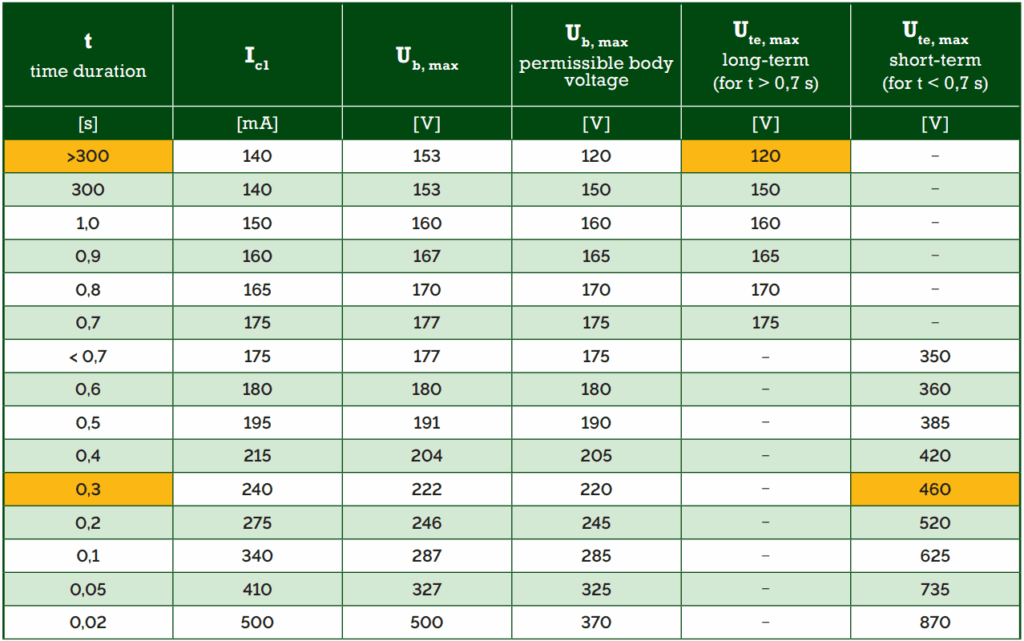
The VLD-F products of the RWVL1 series are available in several versions with different triggering voltages. The choice of the triggering voltage primarily depends on the speed of the short-circuiting emergency disconnectors in the traction power substations. In fact, the amplitude of the permissible touch voltages for the safety of passengers and traction operators depends on the exposure duration on a person.
In general, the shorter the exposure time, the higher the amplitude of the touch voltage can be. This relationship is specified in EN 50122-1 in the table 1 below (this applies specifically for DC touch voltages).
This means that if, for example, the disconnection of the traction power substation in case of shortcircuit takes place within less than 0.3 s, you can use a VLD with a triggering voltage less than 460 V. The maximum triggering voltage for long or unknown disconnector reactions is 120 V. The goal is to achieve some compromise so that there is no unintended activation of the VLD by an accidental short pulse of low amplitude (i.e., a „safe“ pulse), but that, with some margin, there is always a correct and fast response of the disconnectors in the power substation during a fatal traction fault.