(Where it is recommended to use the class 2 VLD)
The main purpose of the VLD class 2 is the protection of passengers and infrastructure against excessive touch voltage and overvoltage caused by trains operation (therefore VLD-O).
New powerful construction
Based on latest customer requirements and the ongoing process of ever-increasing demands on traction performance, the RW company has developed a new, fully solid-state Voltage Limiting Device (VLD) class 2, with the market highest repeatable current load and possibility of remote indication of the VLD status. The current is quickly switched by powerful thyristors when the permissible touch voltage is exceeded. Thanks to high recoverable thyristor current and robust heatsinks our VLD-O is capable to bear more than 3 kA for 30 seconds (it is typical time needed for train acceleration or recuperative braking). Due to massive aluminum body the VLD has huge thermal capacity and therefore can bear extremely high currents for time when heavy trains accelerate or brake. Thanks to high surface of heat sinks it needs just short time to radiate this accumulated energy to surrounding to be ready to manage next train approach or departure. It means that class 2.x VLD is able repeatably protect passengers and technology under the most demanding condition.
To passengers and technology protection (including inner electronics of VLD), the VLD is equipped by set of high energy varistors (A2 surge arrester) which react within 30ns to lightning strike or dangerous pulses from traction. Moreover, an autonomous (does not need an external power supply) internal triggering electronics allows a different response to short pulses with higher voltage amplitude and long-lasting pulses. This behavior is allowed by the touch voltage limits set by the EN 50122-1 standard. In practice, this means that the VLD operates in three switching sequences – the varistors react immediately to a voltage potential higher than 350 V. The semiconductor electronics then switch within 1 millisecond if the track potential exceeds the UTi limit (see technical data below). However, if the voltage is lower than UTi but higher than UTn, the VLD response is delayed, typically by 10 milliseconds. This setting allows you to limit the amount of leakage currents through the VLD to a minimum in situations where short pulses with higher voltage levels do not endanger the safety of passengers (remember, that 1A@1year of stray current is able to transfer up to 8 kgs steel from metallic or reinforced concrete infrastructure!!!). The standard delay settings are 1 (UTi) and 10 (UTn) milliseconds, but both delay intervals and the levels of both triggering voltages can be changed according to agreement with the user.
Although the repeatable load parameters of our VLD Class 2 are currently the best, in exceptional cases, damage to the power thyristors can occur under very extreme loads (for example, in the event of a short circuit near a very powerful substation). In such cases, it is desirable that the traction operator is informed as soon as possible about such a failure to prevent long-term leakage of stray currents that cause severe corrosion on the infrastructure along the tracks. For this reason, our VLDs are equipped with a patented overload sensor, which can be connected to a wireless communication device that immediately sends information about the failure remotely. You can see this information from virtually anywhere in the world within few seconds. This also saves the operator OPEX (OPerating EXpenditures) that are currently spent on costly inspection and manual testing of installed VLDs, consisting in frequent physical inspection of the installed VLDs,
which is a challenging task because a reliable verification of the function necessitates to disconnect the VLD from the rail,
perform impedance and triggering voltage measurements followed with reconnection of the VLD-F to the rail. This takes
quite a lot of time (min. 10 minutes for approx. 3 workers) and costs considerable operating money, so that the intervals between checks are often extended and the risk of damage to the infrastructure increases disproportionately. Another advantage of this solution is the significantly simpler and more transparent logistics, because in addition to the indication of
immediate necessity to replace the VLD, other identification parameters of the VLD to be inspected (e.g. serial number, installation coordinates, etc.) are stored in the server memory, which can then be used as a basis for operational statistics, analyses, etc. Simply, this is a good base for predictive maintenance and integration of VLDs to the traction system via IoT platform.
How to apply class 2.1 or class 2.2?
Recoverable VLD-F
For many years it has been common practice to install simple VLD-F anywhere alongside DC and AC powered railway lines. This installation has often not been associated with infrastructure corrosion problems. With increasing traffic on the lines, changing power supply infrastructure and train propulsion systems, infrastructure failures and damages appear more frequently, which can be clearly attributed to improperly installed VLD-Fs designed on the basis of gas discharge tubes (GDT). The crux of the problem lies in the combination of the behavior of GDT at different voltage levels and details can be found in our VLD-F flyer.
To prevent such a problem and save operational expenditures it is recommended to use a repeatable, solid-state VLD-F class
2.2 there. The higher initial investment will quickly pay for itself in the form of long-term stable operation, protective function and minimal corrosion of the infrastructure. The recoverable VLD-F must, of course, meet the criteria for a safe response of the substation emergency disconnector at the moment of a traction short circuit. Therefore, it is necessary to select a VLD with sufficient repeatable short-circuit capacity (Iw(r)) for this application. The solid-state VLD-F will, of course, operate above this current level, but will go into a permanent short circuit state and must then be replaced. For timely
replacement, we recommend installing the remote VLD-F status monitoring system.
Recoverable VLD-O class 2.1
In situations where there is a risk of exceeding the permissible touch voltage even during normal train operation, a so-called
VLD-O must be installed. Typical locations are places far from power stations, operation of heavy trains with high current
consumption, etc. There are several other ways to reduce this dangerous voltage, but adding substations, a third return wire
and similar methods involve large investments, and proper using a powerful VLD-O may be the optimal way.
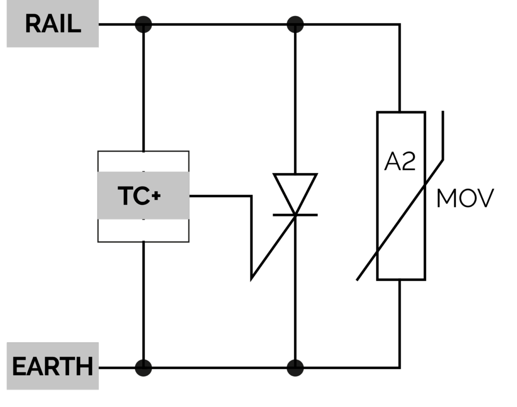
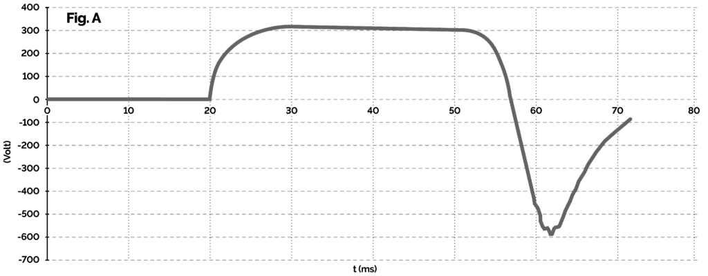
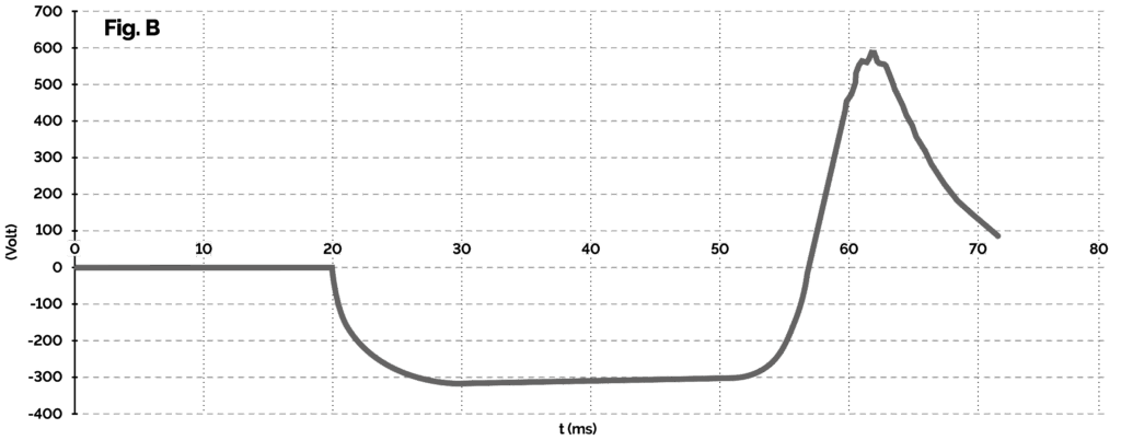
However, caution should be exercised when applying VLD class 2.1 in situations where longer pulses (i.e. longer than approximately 1 ms) of both polarities can be expected on the return conductor. This means in situations where the OCL falls, the insulator short-circuits, during energy recuperation, in locations far from the substation, etc. Let us show the reasons for this statement with an example – the situation of an OCL drop and the reaction of traction to a short-circuit current. The class 2.1 VLDs available today have integrated high-energy varistors, which have two tasks. One is functional, i.e. to react quickly at the moment of a highvoltage pulse by switching on and limiting the touch voltage, and the second is protective, i.e. to protect electronic circuits and power thyristor in the class 2.1 VLD from highvoltage pulses. At the moment of a fault, the varistors react immediately and with a certain delay (typically around 1 ms) the thyristors then take over the short-circuit current. In the case of class 2.1 VLDs, where only a single thyristor is installed, only the varistors take over all the energy load in the reverse voltage direction. This can cause them to be overloaded to the point where the VLD is irreversibly damaged. See typical envelope of rail voltage against earth at short-circuit place (fig.A) or at substation (fig.B).
In both cases, it can be seen that the rail-to-ground voltage is present in both polarities for tens of milliseconds. This means that in both cases, high currents will flow through the varistors in the reverse direction (i.e. in the direction where the thyristor is not installed) for a relatively long time, which will destroy the varistors. These pictures show an „ideal“ situation, i.e. a failure where the broken OCL falls directly onto the return circuit (rail). In the case where the OCL falls off the track, the values can be significantly worse and more dangerous. This means that a class 2.1 can be used as a VLD-O (under certain conditions – single polarity, low induction of loop, no recuperation, …), but its deployment in VLD-O+F mode is mostly destructive.
Recoverable VLD-O class 2.2
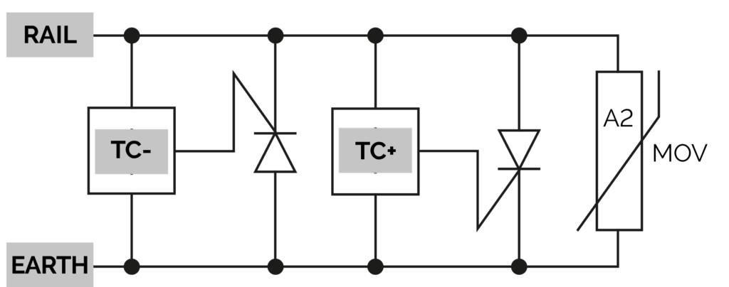
VLD class 2.2 type VLD-O+F is the optimal choice for a combined solution of protection against touch voltage both in case of traction failure and during train operation. In particular, VLD with high short-term (<100ms) and medium-term (30 sec) repeatable currents are the ideal choice for long-term protection. Repeatability ensures a long-term device life (30+ years)
and minimal investment and operating costs, especially if it is supplemented with remote status signaling. Two anti-parallel
connected power thyristors in conjunction with a set of varistors react repeatably in all possible dangerous situations at any point of DC or AC traction (any polarity of voltage). Due to the constantly increasing demands on traction performance, when choosing a suitable VLD, it is necessary to take into account not only actual requirements, but also the foreseeable development of traction in the next 30 years (increase in performance, number of trains, introduction of recuperation, etc.). VLDs with high repeatable loads are intended for applications where performance increases can be expected in the future.
When selecting the switching voltage, it is necessary to follow national regulations and the EN 50122-1 standard. Typical values of UTn are 120V in passenger stations, 60V in workshops and 350V in non-public parts of the track.
However, we are ready to manufacture VLDs with UTn values according to your requirements. For the powerful application of class 2.x VLDs in the maintenance-free VLD-O and VLD-F modes, the parameters of repeatable currents (rated current Ir
and short time withstand current Iw(r)) are important. The rated current values express the ability of the VLD to accumulate and radiate thermal energy generated during the processing of long-term currents or currents with high amplitude in the VLD-O mode (i.e. during train operation). The values of the short time withstand currents then define the ability of the VLD to repeatedly respond to fault situations (short circuits, OCL failures, etc.). Higher values mean trouble-free long-term operation without additional costs even in the demanding conditions of modern powerful tractions and with regard to their future development. The exceptional repeatable load values of RW brand VLDs often allow class 2 VLDs to be installed in places where it was necessary to use powerful (and expensive) class 4 VLDs. For this purpose, class 2 VLDs can optionally be equipped with electronic monitoring circuits where desired. For extreme loads, our VLDs can be equipped with robust heat sinks; conversely, where lower current durations and amplitudes can be expected, cheaper VLDs without heat sinks (just “body”) can be used.
If you need more application details or consultancy, don´t hesitate to contact us, please.